C Ionian     C  D  E  F  G  A  B    C Major
C Dorian     C  D  Eb F  G  A  Bb   Bb Major
C Phrygian   C  Db Eb F  G  Ab Bb   Ab Major
C Lydian     C  D  E  F# G  A  B    G Major
C Mixolydian C  D  E  F  G  A  Bb   F Major
C Aeolian    C  D  Eb F  G  Ab Bb   Eb Major
C Locrian    C  Db Eb F  Gb Ab Bb   Db Major

Since C Ionian has no altered notes, we can use that as a very nice baseline

Ionian      - No Changes
Dorian      - b3 b7
Phrygian    - b2, b3, b6, b7
Lydian      - #4
Mixolydian  - b7
Aeolian     - b3, b6, b7
Locrian     - b2, b3, b5, b6, b7

So if we simply apply this formula to a major/ionian scale, we transform it into that mode.

A husband, a father of 7, a runner training for 2 marathons this year as a Hammer Nutrition sponsored athlete,a guitar player,a digital artist and a computer programmer by day. I got this.
Showing posts with label Reference. Show all posts
Showing posts with label Reference. Show all posts
Monday, January 19, 2009
Learning Modes - Some formulas
Once you start getting the idea of modes, one of the easiest ways to deal with them is knowing how they are spelled relative to their ionian version. We can Use the key of C as a great example.


Tuesday, January 13, 2009
Learning Modes - Another Step
In my last post, we looked at a very simple chord progression with a couple of chords. Most likely you will be playing music that is much more complicated. So what happens when a Cm shows up in your song in G major? There is a note in that chord that is not in your key! Well there are a couple things you can do here.
Now if we use this chart we can easily get our list of available modes for many chords that may be in our tune. If we run across an Ab major chord in our key of G tune (which would be a bII), we see that G phrygian (Eb Major) or G Locrian (Ab Major) might work well. Which would make sense since playing Ab major over an Ab Major chord would make sense.
- Do not play an E during this chord
- Switch to C Minor
- Find some other mode that works
Well option 1 is simple enough, but we want to spice things up a little. Option 2 and 3 actually go together. If we look closely at C minor, we find that it is 3 flats. Bb,Eb,Ab. Now by looking at the key signature, we see that the relative Major to C minor is Eb Major. If we look at the relative Majors to modes of G, we have G-F-Eb-D-C-Bb-Ab. So Eb Major == 3rd mode of G, which is G Phrygian. To see what other modes of G we could play over this Cm chord, we simply need to see which of the modes of G contain a Cm chord. Well since Cm is C-Eb-G we can see that Eb Major, Bb Major and Ab Major have Eb's in them (as well as C's and G's). So our options for playing over a Cm in G are
- G Phrygian (Eb Major)
- G Aeolian/minor (Bb Major)
- G Locrian (Ab Major)
Get ready for a little bit of information overload. If we take the notes of the modes of G
G Ionian     G A  B  C  D  E  F#  G Major
G Dorian     G A  Bb C  D  E  F   F Major
G Phrygian   G Ab Bb C  D  Eb F   Eb Major
G Lydian     G A  B  C# D  E  F#  D Major
G Mixolydian G A  B  C  D  E  F   C Major
G Aeolian    G A  Bb C  D  Eb F   Bb Major
G Locrian    G Ab Bb C  Db Eb F   Ab Major
and then figure out what all the triads are
Ionian         G  Am Bm  C   D  Em F#°
Dorian         Gm Am Bb  C   Dm E° F
Phrygian       Gm Ab Bb  Cm  D° Eb Fm
Lydian         G  A  Bm  C#° D  Em F#m
Mixolydian     G  Am B°  C   Dm Em F
Aeolian        Gm A° Bb  Cm  Dm Eb F
Locrian        G° Ab Bbm Cm  Db Eb Fm
we can make a list of the modes that contain each chord
G   Ionian,Lydian,Mixolydian
Gm  Dorian,Phrygian,Aeolian
G°  Locrian
A   Lydian
Am  Ionian,Dorian,Mixolydian
Ab  Phrygian,Locrian
A°  Aeolian
Bm  Ionian,Lydian
B°  Mixolydian
Bb  Dorian,Aeolian,Phrygian
Bbm Locrian
C   Ionian,Dorian,Mixolydian
Cm  Phrygian,Aeolian,Locrian
C#° Lydian
D   Ionian,Lydian
Dm  Dorian,Mixolydian,Aeolian
D°  Phrygian
Db  Locrian
Em  Ionian,Lydian,Mixolydian
E°  Dorian
Eb  Phrygian,Aeolian,Locrian
F#° Ionian
F#m Lydian
F   Dorian,Mixolydian,Aeolian
Fm  Phrygian,Locrian
Then we can generalize them into a more portable method using chord numbers
I     Ionian,Lydian,Mixolydian
i     Dorian,Phrygian,Aeolian
i°    Locrian
II    Lydian
ii    Ionian,Dorian,Mixolydian
ii°   Aeolian
bII   Phrygian,Locrian
iii   Ionian,Lydian
iii°  Mixolydian
bIII  Dorian,Aeolian,Phrygian
biii  Locrian
IV    Ionian,Dorian,Mixolydian
iv    Phrygian,Aeolian,Locrian
#iv°  Lydian
V     Ionian,Lydian
v     Dorian,Mixolydian,Aeolian
v°    Phrygian
bV    Locrian
vi    Ionian,Lydian,Mixolydian
vi°   Dorian
bVI   Phrygian,Aeolian,Locrian
vii°  Ionian
vii   Lydian
bVII  Dorian,Mixolydian,Aeolian
bvii  Phrygian,Locrian
Now if we use this chart we can easily get our list of available modes for many chords that may be in our tune. If we run across an Ab major chord in our key of G tune (which would be a bII), we see that G phrygian (Eb Major) or G Locrian (Ab Major) might work well. Which would make sense since playing Ab major over an Ab Major chord would make sense.
Does this mumbo jumbo make sense? Have I made a chordal miscalculation? Sound off in the comments.
Monday, January 05, 2009
Learning Modes - Finding the Relative Major
In my last article on modes we discussed how you can find a given mode by playing a major scale at a given interval from the original note.
First take a look at this slightly confusing table.
If you look at this chart you will get a quick reference to where you will find the scale you are needing.
Lets take a example:
Say we are playing a G major chord, we have 3 mode options that might sound good with it. Ionian, Lydian and Mixolydian since they are the 3 "major" tonality modes (that is the 3rd is a major 3rd in the mode). So how do we get to G Ionian, G Lydian and G Mixolydian? I always have an easier time going up an interval rather than down so in the chart above, I have converted the intervals down from the WWHWWWH pattern we talked about in the previous article to ascending intervals.
So now we can grab a mode from a given chord.
First take a look at this slightly confusing table.
| Mode | Tonality | Steps Down | 1/2 Steps Down | Interval Down | 1/2 Steps Up | Interval Up |
| Ionian (Major) | Major | 0/12 | Unison/Octave | 12/0 | Unison/Octave | |
| Dorian | Minor | W | 2 | Major 2nd | 10 | Minor 7th |
| Phrygian | Minor | WW | 4 | Major 3rd | 8 | Minor 6th |
| Lydian | Major | WWH | 5 | Perfect 4th | 7 | Perfect 5th |
| Mixolydian | Major / Dom | WWHW | 7 | Perfect 5th | 5 | Perfect 4th |
| Aeolian (Minor) | Minor | WWHWW | 9 | Major 6th | 3 | Minor 3rd |
| Locrian | Diminished | WWHWWW | 11 | Major 7th | 1 | Minor 2nd |
| (Ionian) | Major | WWHWWWH | 12/0 | Unison/Octave | 0/12 | Unison/Octave |
If you look at this chart you will get a quick reference to where you will find the scale you are needing.
Lets take a example:
Say we are playing a G major chord, we have 3 mode options that might sound good with it. Ionian, Lydian and Mixolydian since they are the 3 "major" tonality modes (that is the 3rd is a major 3rd in the mode). So how do we get to G Ionian, G Lydian and G Mixolydian? I always have an easier time going up an interval rather than down so in the chart above, I have converted the intervals down from the WWHWWWH pattern we talked about in the previous article to ascending intervals.
- G Ionian = G Major, since Ionian = Major
- G Lydian is the major scale starting a perfect 5th above the scale in question. So a perfect 5th above G is D. So G Lydian = D Major
- G Mixolydian is the major scale starting a Perfect 4th above the note in question which is C, so G Mixolydian = C Major.
- A minor 7th above F is Eb. Eb Major is F dorian
- A minor 6th above F is Db.Db Major is F Phrygian
- A minor 3rd above F is Ab. Ab Major is F Aeolian
So now we can grab a mode from a given chord.
Monday, December 01, 2008
Guitar Article Index
Music / Guitar Articles
While there has been a rise in popularity in games like Guitar Hero and Rock Band, there has been a secondary effect of having a renewed interest in music as a whole. The past year has a marked a dramatic increase in the amount of people either asking for guitar lessons or for advice on what new guitar gear they should get for themselves or their child. So in response to that, interest, I have started writing a series of articles to help explain some gear as well as give a little advice into this area. In the future, I'll also be writing some gear reviews as well as some more advanced gear articles.
Starting Gear ArticlesChoosing a Guitar Coming Soon... Effects - Multi Effects | Advanced Gear ArticlesComing SoonGear Reviews Coming Soon |
Saturday, November 22, 2008
XNA Series - Begining 3D - Part 1
I have been wanting to get some posts on here about 3D. But since it is a much more complex subject than 2D, I have been holding off as I am still getting my head around it. Perhaps we can work through this together and see what we come up with.
To start drawing in 3D, we need a model. I recommend something like Blender3D, since it has all the tools you need to create a working 3d model that you can import into XNA. This is not a tutorial about modeling in blender, perhaps I'll do that later. But once you have a model created in Blender, you want to export it in Autodesk FBX format. You can load that into your content pipeline in the same way you import a sprite. The difference is in the type of C# object we create to load it into. Rather than a texture2d object, we load in this model as a Model object. We will also create a Vector3 object to set it's position rather than a Vector2, since we need to put this model in 3d space.
Project Files
Vector3 camPos will store the location of our 3d camera. Our 3d camera can be thought of as a video camera placed into the 3d world at a given location.
camLookAt is a point at which our camera will be pointed in 3d space.
the 2 Matrices camProj and camView are somewhat more complicated and we will set them up later.
To load in our Model's data, in LoadContent we will do this
tower = Content.Load<model>("tower");
that should look familiar, since it is the same way we loaded in images. Except we make sure to tell the Load function it is dealing with Model objects rather than Texture2D.
Next we initialize the camView matrix
camView = Matrix.CreateLookAt(camPos, camLookAt, Vector3.Up);
We create a 4x4 matrix from the position of the camera and the point it is looking at. This matrix gives us a way to alter the way we see the model so that it looks like we are seeing it from the camera. Then we set up the projection matrix
camProj = Matrix.CreatePerspectiveFieldOfView(
MathHelper.ToRadians(45.0f),
graphics.GraphicsDevice.Viewport.AspectRatio,
1.0f,
10000.0f);
which will alter the way we see the model in perspective. We pass this method the width of our view field (45 degrees). the aspect ratio of our graphics device and the near and far limits to what we can see (clipping planes). If you don't fully understand these matrix operations, its ok, just press on for now.
We are almost there, we need to create a method that applies all these things to our model. Since we will want to draw more than one model in the future, we will make a generic function. We call it DrawModel and will pass it a model to be drawn, it's position and a scale (to make it bigger or smaller). In a model object we can have many meshes. So we need to loop through them all. Then each mesh has a list of "BasicEffects" which control how that mesh will be drawn, so we loop through those too. For each basic effect we will do the following
To start drawing in 3D, we need a model. I recommend something like Blender3D, since it has all the tools you need to create a working 3d model that you can import into XNA. This is not a tutorial about modeling in blender, perhaps I'll do that later. But once you have a model created in Blender, you want to export it in Autodesk FBX format. You can load that into your content pipeline in the same way you import a sprite. The difference is in the type of C# object we create to load it into. Rather than a texture2d object, we load in this model as a Model object. We will also create a Vector3 object to set it's position rather than a Vector2, since we need to put this model in 3d space.
Project Files
The next 4 objects in our game class declarations are a little more complex.
Model tower;
Vector3 pos = Vector3.Zero;
Vector3 camPos = new Vector3(0.0f, 60.0f, 160.0f);
Vector3 camLookAt = new Vector3(0.0f, 50.0f, 0.0f);
Matrix camProj;
Matrix camView;
Vector3 camPos will store the location of our 3d camera. Our 3d camera can be thought of as a video camera placed into the 3d world at a given location.
camLookAt is a point at which our camera will be pointed in 3d space.
the 2 Matrices camProj and camView are somewhat more complicated and we will set them up later.
To load in our Model's data, in LoadContent we will do this
tower = Content.Load<model>("tower");
that should look familiar, since it is the same way we loaded in images. Except we make sure to tell the Load function it is dealing with Model objects rather than Texture2D.
Next we initialize the camView matrix
camView = Matrix.CreateLookAt(camPos, camLookAt, Vector3.Up);
We create a 4x4 matrix from the position of the camera and the point it is looking at. This matrix gives us a way to alter the way we see the model so that it looks like we are seeing it from the camera. Then we set up the projection matrix
camProj = Matrix.CreatePerspectiveFieldOfView(
MathHelper.ToRadians(45.0f),
graphics.GraphicsDevice.Viewport.AspectRatio,
1.0f,
10000.0f);
which will alter the way we see the model in perspective. We pass this method the width of our view field (45 degrees). the aspect ratio of our graphics device and the near and far limits to what we can see (clipping planes). If you don't fully understand these matrix operations, its ok, just press on for now.
We are almost there, we need to create a method that applies all these things to our model. Since we will want to draw more than one model in the future, we will make a generic function. We call it DrawModel and will pass it a model to be drawn, it's position and a scale (to make it bigger or smaller). In a model object we can have many meshes. So we need to loop through them all. Then each mesh has a list of "BasicEffects" which control how that mesh will be drawn, so we loop through those too. For each basic effect we will do the following
- enable lighting
- set lighting preferences
- set the World, Projection and View transformation matrices for the effect
void DrawModel(Model model, Vector3 modelPosition,float scale)
       {
           foreach(ModelMesh mesh in model.Meshes){
               foreach (BasicEffect effect in mesh.Effects)
               {
                   effect.EnableDefaultLighting();
                   effect.PreferPerPixelLighting = true;

                   effect.World =
                       Matrix.CreateTranslation(modelPosition)*
                       Matrix.CreateScale(scale)
                       ;

                   effect.Projection = camProj;
                   effect.View = camView;
               }
               mesh.Draw();
           }
       }

All that is left at this point is to call DrawMesh from our Draw method with appropriate parameters.

DrawModel(tower, pos,10f);

I've added a couple extra calls to DrawModel in the project file so you can see a little "scene"
Friday, November 21, 2008
Free Chord and Scale Diagram Paper
In teaching guitar I spend a lot of time teaching my students chords and scales. I have several pages that I have made up with chords and scales on them, but they are a bit much for the beginner. Too many chords or too many scales that it is hard to focus. So I generally like to write out the couple of scales or chords that I want them to practice for that week on a sheet of paper. But again if I make them too small they are hard to read from. So I created some nice sheets you can print off with 9, 4 fret chord blocks and 6, 8 fret scale blocks. So I hope there are helpful to you.
These links are fixed now. Sorry for the previous inconvenience.
Chord Blocks
Scale Blocks
These links are fixed now. Sorry for the previous inconvenience.
Chord Blocks

Scale Blocks

Monday, November 03, 2008
XNA Series - AI - Better Steering - Part 1
I have been reading Steering Behaviors For Autonomous Characters by Craig Reynolds and after several reads I have decided to try to implement it in my own code and I think I am ready to explain it to you my loyal reader.
In his paper Mr Reynolds take a different approach that we have been taking thus far. Rather than having our steering be a simple rotation and moving forward at a set speed. He takes several other aspects into consideration, making a much more detailed simulation. To start we think about it in these terms: First we decide what direction and "magnitude" we need to move in that direction to steer us toward our goal. This is called our "Steering Vector". If we applied the steering vector all at once, we would immediately be put on the right path, but that would make for a very non-realistic simulation. Instead, rather, in the application of the steering vector, we take into consideration our current velocity, direction, mass and maximum force we can exert. We then factor these items against our steering vector to get an acceleration in a new direction to be added to our current velocity, we truncate this new velocity to our maximum speed and in that timestep we take a step towards steering to our goal.
The benefit of this method really lies in the Steering Vector. Since vectors can be scaled, added, subtracted, etc. We could apply several steering vectors. Say an object was following waypoints, we could say if an enemy is within a given distance, add the Flee steering vector times 50% and the Waypoint vector times 50%. We would then apply this new steering vector rather than just Waypoint or Flee, so that the object is still trying to do the waypoints, while evading.
In my next post, I will start looking at how we can adapt this method into our GameObject class.
The paper to which I am referring.
In his paper Mr Reynolds take a different approach that we have been taking thus far. Rather than having our steering be a simple rotation and moving forward at a set speed. He takes several other aspects into consideration, making a much more detailed simulation. To start we think about it in these terms: First we decide what direction and "magnitude" we need to move in that direction to steer us toward our goal. This is called our "Steering Vector". If we applied the steering vector all at once, we would immediately be put on the right path, but that would make for a very non-realistic simulation. Instead, rather, in the application of the steering vector, we take into consideration our current velocity, direction, mass and maximum force we can exert. We then factor these items against our steering vector to get an acceleration in a new direction to be added to our current velocity, we truncate this new velocity to our maximum speed and in that timestep we take a step towards steering to our goal.
The benefit of this method really lies in the Steering Vector. Since vectors can be scaled, added, subtracted, etc. We could apply several steering vectors. Say an object was following waypoints, we could say if an enemy is within a given distance, add the Flee steering vector times 50% and the Waypoint vector times 50%. We would then apply this new steering vector rather than just Waypoint or Flee, so that the object is still trying to do the waypoints, while evading.
In my next post, I will start looking at how we can adapt this method into our GameObject class.
The paper to which I am referring.
Friday, October 31, 2008
XNA - Simulating Gravity
Now that we have talked a little about vectors and acceleration and such, lets put together a simple 'game' that takes a few of these things together. We will create a Game Object like we have been doing, but we are going to add an Update method to it that will move the updating of our object inside of it rather than outside.
So we pass the current gameTime into the object and check our location. If we are above 400 all we will do is acellerate based on gravity. Now Real gravity is -9.8 meters per second squared. So since we move "down" in XNA terms by adding to Y rather than subtracting, our Gravity velocity will be 9.8. Now 9.8 is relative in pixels So we are basically saying that 1 pixel is one meter. We could of course scale this. If our sprite is a person and is 25 pixels high and "in real life" that person is 2 meters tall, then really we want 12.5 pixels to represent a meter. So in that case we would scale any acellerations by 12.5 to get a more physically accurate simulation. You will also notice that my acceleration vector is not just [0,9.8] but instead I am multiplying by something you have not yet seen. gameTime.ElapsedTime.TotalSeconds. This is a representation in factional seconds of how long it has been since the last update. So since 9.8 is supposed to be per one second, if we multiply that by how long it has actually been (say 0.02 seconds) we will just get enough for the time that has past. That way no matter how fast or slow our program runs, the gravity acceleration should stay constant.
The only other thing that I am doing here is if my object falls below the 400 pixel mark. I make it bounce. I do this by negating it's Y velocity and scaling it back a little. The closer I scale the Y velocity to 0 the less it bouces back. If I scale it higher that 1 it will bounce higher then when it started in the first place.
Here are the project files.
       public void Update(GameTime gameTime)
       {
           if (position.Y < 400)
           {
               velocity += new Vector2(0f, (float)(9.8 * gameTime.ElapsedGameTime.TotalSeconds));
           }
           else
           {
               velocity.Y = velocity.Y * -0.8f;
           }
           position += velocity;
       }
So we pass the current gameTime into the object and check our location. If we are above 400 all we will do is acellerate based on gravity. Now Real gravity is -9.8 meters per second squared. So since we move "down" in XNA terms by adding to Y rather than subtracting, our Gravity velocity will be 9.8. Now 9.8 is relative in pixels So we are basically saying that 1 pixel is one meter. We could of course scale this. If our sprite is a person and is 25 pixels high and "in real life" that person is 2 meters tall, then really we want 12.5 pixels to represent a meter. So in that case we would scale any acellerations by 12.5 to get a more physically accurate simulation. You will also notice that my acceleration vector is not just [0,9.8] but instead I am multiplying by something you have not yet seen. gameTime.ElapsedTime.TotalSeconds. This is a representation in factional seconds of how long it has been since the last update. So since 9.8 is supposed to be per one second, if we multiply that by how long it has actually been (say 0.02 seconds) we will just get enough for the time that has past. That way no matter how fast or slow our program runs, the gravity acceleration should stay constant.
The only other thing that I am doing here is if my object falls below the 400 pixel mark. I make it bounce. I do this by negating it's Y velocity and scaling it back a little. The closer I scale the Y velocity to 0 the less it bouces back. If I scale it higher that 1 it will bounce higher then when it started in the first place.
Here are the project files.
Wednesday, October 29, 2008
XNA Sidebar - More Vectors
Another thing that vectors can do for us is handle acceleration. We already talked about moving at a certain velocity (distance and direction) but what happens if we want to continue on that path or speed up or turn in a new direction. We have to accelerate or slow down or have force applied to us in a new direction. If our object has a position P and a current velocity of [3,3] which means at every timestep we move 3 in the x direction and 3 in the y direction. If we want to speed up to [10,10] we could of course just set our velocity to [10,10], but that is very unrealistic. That would be like getting in your car and going 30 miles per hour, pressing the gas and in one microsecond be going 100 mph! The sheer force of that acceleration alone would probably kill you. Depending on your mode of transportation you have limits to how fast you can accelerate. This is defined by how much mass you have and how much force you can exert. Because if you took high-school physics, you may remember this.
F=ma
Which means: Force = Mass x Acceleration. This is Newton's Second Law of Motion. We would know the mass of our object ( say your vehicle weighs ton in english measurements. Which is approx 907kg) and we decide it should be able to go from 0 to 30 meters per second (which is about 60 miles per hour, use google to do your conversions!) in 10 seconds. Now we will assume for our simulation that acceleration is constant, that means every second we would need to go 3 meters per second faster. So we want to acellerate at a maximum of 3 m/s^2. So our maximum force is
907kg * 3 m/s^2 = 2721 Newtons or (kg*m/s^2)
But how do we apply this to vectors?
Well first we need to know our desired velocity. In my car example before we were going 30 mph and our desired velocity was 100mph (naughty speeder) That is velocity in 1 direction. Now lets think in 2. our current velocity is the vector [0,0] and we want to go [10,10] we cannot just jump from one to the other. In this case we can actually use the length of the vector to represent the force we would have to apply to go from one to the other. In this case the length of the vector is 14.14 well, say we determine that our maximum force is a vector length of 2, we truncate our desired vector to a length of 2 (we leave it alone if it is less than that already) and that gives us a vector which is the maximum force vector which we can apply to our object. So now that we have force, we divide that by the mass of our object say 10kg and that gives us our acceleration vector. Now for each timestep we do this calculation and add our acceleration vector to our current velocity to get our new accelerated velocity. We do have to truncate our velocity to our maximum speed since the length of our velocity vector is equal to our speed. Then we simply add our velocity vector to our position point and we have our new position for that timestep.
So some things we learned about vector lengths...
Length of the Vector between 2 velocity vectors is the total force required to accelerate from one to the other.
Then length of the velocity vector is the current speed
The Acceleration vector is gained by Dividing the Force vector by the mass of the object
The Acceleration vector is added to the velocity vector each time step to gain a new velocity.
Did I get something wrong? If you know more about this than me, please contribute by commenting below!
F=ma
Which means: Force = Mass x Acceleration. This is Newton's Second Law of Motion. We would know the mass of our object ( say your vehicle weighs ton in english measurements. Which is approx 907kg) and we decide it should be able to go from 0 to 30 meters per second (which is about 60 miles per hour, use google to do your conversions!) in 10 seconds. Now we will assume for our simulation that acceleration is constant, that means every second we would need to go 3 meters per second faster. So we want to acellerate at a maximum of 3 m/s^2. So our maximum force is
907kg * 3 m/s^2 = 2721 Newtons or (kg*m/s^2)
But how do we apply this to vectors?
Well first we need to know our desired velocity. In my car example before we were going 30 mph and our desired velocity was 100mph (naughty speeder) That is velocity in 1 direction. Now lets think in 2. our current velocity is the vector [0,0] and we want to go [10,10] we cannot just jump from one to the other. In this case we can actually use the length of the vector to represent the force we would have to apply to go from one to the other. In this case the length of the vector is 14.14 well, say we determine that our maximum force is a vector length of 2, we truncate our desired vector to a length of 2 (we leave it alone if it is less than that already) and that gives us a vector which is the maximum force vector which we can apply to our object. So now that we have force, we divide that by the mass of our object say 10kg and that gives us our acceleration vector. Now for each timestep we do this calculation and add our acceleration vector to our current velocity to get our new accelerated velocity. We do have to truncate our velocity to our maximum speed since the length of our velocity vector is equal to our speed. Then we simply add our velocity vector to our position point and we have our new position for that timestep.
So some things we learned about vector lengths...
Length of the Vector between 2 velocity vectors is the total force required to accelerate from one to the other.
Then length of the velocity vector is the current speed
The Acceleration vector is gained by Dividing the Force vector by the mass of the object
The Acceleration vector is added to the velocity vector each time step to gain a new velocity.
Did I get something wrong? If you know more about this than me, please contribute by commenting below!
Tuesday, October 28, 2008
XNA Sidebar - Intro To Vector Math
 I am not a math wiz, but I know enough to get around. I wrote my Sidebar article on Trigonometry to explain a few concepts that people might want to know to better program in XNA. Well according to my site metrics, it quicky became one of my most viewed pages. So apparently it was info people wanted to know! Well in that same spirit, I give you my intro to vectors post.
Vectors in 2 dimensions are relatively easy concepts, especially when you can visualize them. They have 2 parts, a direction and a magnitude. We can write them as a simple coordinate like [7,8]. Now, although this looks more like a point (and you are right) if we consider this as relative to another point, say (0,0) we now have a vector. As you can see the vector in the image has a direction and a length. In this case the length could be found by the Pythagorean theorem. where A is the x length and B is the Y length. So the length of this vector is the square root of 7 squared + 8 squared, which is 10.63.
One of the simplest operations we can do to a vector is addition. Say we take our vector [7,8] and add [1,3]. If we look at example B, we see the 2 vectors. But when we add them, we simply add their 2 components. Thus resulting in a new vector [8,11]. Which makes more sense if we look at example C where we have stacked the first
 2 vectors. That is went from the endpoint of the first vector and moved 1 in the x direction and 3 in the Y. The same goes for subtraction, just minus instead of plus
Multiplication is another useful tool for Vectors. when we multiply a vector times a scaler (a single number) it "scales" the vector to a new length. So if we say [3,4] * 2 we end up with the vector [6,8] which is 2 times as long as the first vector. See Example D. Want some proof? The length of the vector [3,4]
LENGTH [3,4]
= SQRT[3^2 + 4^2]
= SQRT[9+16]
= SQRT[25]
= 5
[3,4] * 2 = [6,8]
LENGTH [6,8]
= SQRT[6^2 + 8^2]
= SQRT[36 + 64]
= SQRT[100]
= 10
and 10 is 2 times 5.
So we have double the length of the vector, but kept the same direction. Much like if we think of a vector as a force being applied to an object in a given direction it will go a certain distance. If we double that force, it will go twice as far. This works the same for division. dividing a vector by 2 will cut it's length in half.
One of the things that we may want to do is find out what the vector that goes in the same direction as this vector, but has a length of 1 is. This is called a unit vector and is gained when we normalize a vector. Luckily for us the XNA Vector2 class has a Normalize method which converts a Vector2 into a unit vector. This is really handy when we have a vector that we want to follow, but it is longer than our current velocity can carry us. Say we want to move from (0,0) to (5,5) we would add the vector (5,5) to position, but say our maximum speed for that movement is only 2. The vector [5,5] would take us aprx 7.07 in that direction. We need to find the vector that is 2 units long in the same direction. We can do that by Normalizing the vector [5,5] and then multiplying it by 2. So we scale it up or down to a length of 1 and then multiply it by the length we actually want it to be. So in c# that would look like this
float maxSpeed = 2;
Vector2 canGo;
Vector2 wantToGo = new Vector2(5,5);
wantToGo.Normalize();
canGo = wantToGo * maxSpeed;
When we multiply this out we get a point that is at [1.14,1.14] This is the vector [5,5] Normalized and multiplied by 2. You are going to see these vector method a lot in our new steering code, because a lot of the time we want to steer further than we are able to move so we have to scale back our vector to a size that we can actually move.
Saturday, October 25, 2008
XNA Series - Showing the Mouse
Here is a quick one for today. You may have noticed that when using your mouse with XNA that it disappears when entering the game area. This is because XNA wants you to determine what your mouse looks like. If you are programming a game with a mouse or cursor type interface (remember that XBOX 360 and Zune gamers do not have mice!) you probably want a custom mouse cursor. Well, it is really very simple. If we take our basic GameObject class (our custom one we have been using, this is not part of the XNA package) and create a instance lets call it mouseObject.
Then in Update we can update it's position
The only other thing that can be helpful here is if your mouse "hotspot" is not in the top left corner, you may want to add an offset value to your gameObject and then in your GameObject.Draw method, do position-offset for the image position. See the attached code sample to see what I did with that (it was an afterthought).
Now you should have your cursor drawn at your mouse's location. You could of course have various cursors in a spritesheet then simply change the source rectangle based on your need.
The source for this post
GameObject mouseObject;and load it up in LoadContent
mouseObject = new GameObject(Content.Load<Texture2D>("mouse"),
                             0,0,
                             new Rectangle(0,0,25,25));
Then in Update we can update it's position
MouseState ms = Mouse.GetState();Then simply call our custom drawing method in Draw
mouseObject.position.X = ms.X;
mouseObject.position.Y = ms.Y;
mouseObject.Draw(spriteBatch);
The only other thing that can be helpful here is if your mouse "hotspot" is not in the top left corner, you may want to add an offset value to your gameObject and then in your GameObject.Draw method, do position-offset for the image position. See the attached code sample to see what I did with that (it was an afterthought).
Now you should have your cursor drawn at your mouse's location. You could of course have various cursors in a spritesheet then simply change the source rectangle based on your need.
The source for this post
Thursday, October 23, 2008
XNA Sidebar - Trigonometry
One area that you may find yourself lacking is in the area of math. Especially when it comes to trig. In this post I want to talk a little about trig and how we can use it in our game programming.
First of it is very good to understand the concept of radians. The trig functions that you will be using in XNA deal with radians, and while you can convert radians to degrees, it is easier to just understand them.
We are used to the idea that a circle is 360 degrees, in radians that is equal to 2π. So all the way around the circle is equal to 0 to apx 6.28 radians, or 0 to 2π radians. Once you go past 2π, you are going around the circle again and can start measuring again. There is a helper function in the MathHelper class called WrapAngle(float angle) that takes a radian measurement and constrains it to -π to π (that is 2π total). So if your Radian Measurment was 3π, it would return a value of π since those 2 angles are equivelent.
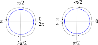
So as you can see from this image, we can look at either making a full circuit around the circle from 0 to 2π or going half a circle π in either direction.
This way we can spin like this in our code and stay within these bounds.
and although it looks like rotation would end up at 100, it actually ends up at -0.5309677 since the WrapAngle maps its value into the -π to π space.
The next question to deal with is this: I am pointing in a given direction and want to move forward 10. How do I determine how much I want to move in the X and Y directions to let me move 10 along my current path. The answer lies in Sin and Cos. If we take a right triangle we can discover the length of a side or an angle if we know 2 of the others. So in this case, we are pointing along the hyp and want to move 10 in that direction. So we want to find the length of the opposite side and the adjacent side. We do this in 2 steps. 1st to find the opposite side (which will be the Y value we add to our current location, we use the Sine function.
Sin(angle) = opposite / hypotenuse
We know the angle from our object's current rotation and we know we want the hyp to be 10 we get this
Sin(rotation) = Y / 10
and if we multiply both sides by 10 we get
10Sin(rotation) = Y
So our Y coordinate for the addition to our current position is 10 times the Sine of our rotation. To get the X coordinate, we do the exact same thing except use the Cosine function. Since
Cos(angle) = adjacent/hyp
In C# it looks like this...
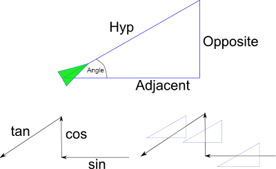
Now how do you remember which is which? Well if you take the image above with the 3 arrows, left arrow, up arrow, down-left arrow and think sin,cos,tan if we superimpose these arrows over 3 triangles you will see that the arrow shows you what order to put the sides in. The left pointing arrow goes over the opposite then the hyp, that is sine. The up arrow goes over adjacent then hyp, that is cosine, the the left-down arrow goes over opposite to adjacent that is tangent.
Now if you already know the 2 sides and need to find the angle instead, you can use the "Arc" versions of sine, cosine and tangent. They look like this
angle = arcsine(opposite/hyp)
angle = arccosine(adjacent/hyp)
angle = arctangent(opposite/adjacent)
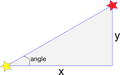
this last one ArcTangent is very helpful if we need to determine at what angle one object is to another. If you look at the example below, if we know the x and y distance from the yellow star to the red star, we can take the arctangent of y/x to get the angle in radians. The 'arc' functions are found in the Math library as Atan, Asin and Acos
So this is a little crash course in Trig. Did it answer your questions? Are there other things you would like me to cover? Let me know, talk back below!
First of it is very good to understand the concept of radians. The trig functions that you will be using in XNA deal with radians, and while you can convert radians to degrees, it is easier to just understand them.
We are used to the idea that a circle is 360 degrees, in radians that is equal to 2π. So all the way around the circle is equal to 0 to apx 6.28 radians, or 0 to 2π radians. Once you go past 2π, you are going around the circle again and can start measuring again. There is a helper function in the MathHelper class called WrapAngle(float angle) that takes a radian measurement and constrains it to -π to π (that is 2π total). So if your Radian Measurment was 3π, it would return a value of π since those 2 angles are equivelent.

So as you can see from this image, we can look at either making a full circuit around the circle from 0 to 2π or going half a circle π in either direction.
This way we can spin like this in our code and stay within these bounds.
for(int i = 0; i< 1000;i++){
rotation = MathHelper.WrapAngle(rotation + 0.1f);
}
and although it looks like rotation would end up at 100, it actually ends up at -0.5309677 since the WrapAngle maps its value into the -π to π space.
The next question to deal with is this: I am pointing in a given direction and want to move forward 10. How do I determine how much I want to move in the X and Y directions to let me move 10 along my current path. The answer lies in Sin and Cos. If we take a right triangle we can discover the length of a side or an angle if we know 2 of the others. So in this case, we are pointing along the hyp and want to move 10 in that direction. So we want to find the length of the opposite side and the adjacent side. We do this in 2 steps. 1st to find the opposite side (which will be the Y value we add to our current location, we use the Sine function.
Sin(angle) = opposite / hypotenuse
We know the angle from our object's current rotation and we know we want the hyp to be 10 we get this
Sin(rotation) = Y / 10
and if we multiply both sides by 10 we get
10Sin(rotation) = Y
So our Y coordinate for the addition to our current position is 10 times the Sine of our rotation. To get the X coordinate, we do the exact same thing except use the Cosine function. Since
Cos(angle) = adjacent/hyp
In C# it looks like this...
float moveDist = 10;
Vector2D movement = new Vector2D();
movement.Y = moveDist * Math.Sin(rotation);
movement.X = moveDist * Math.Cos(rotation);

Now how do you remember which is which? Well if you take the image above with the 3 arrows, left arrow, up arrow, down-left arrow and think sin,cos,tan if we superimpose these arrows over 3 triangles you will see that the arrow shows you what order to put the sides in. The left pointing arrow goes over the opposite then the hyp, that is sine. The up arrow goes over adjacent then hyp, that is cosine, the the left-down arrow goes over opposite to adjacent that is tangent.
Now if you already know the 2 sides and need to find the angle instead, you can use the "Arc" versions of sine, cosine and tangent. They look like this
angle = arcsine(opposite/hyp)
angle = arccosine(adjacent/hyp)
angle = arctangent(opposite/adjacent)
this last one ArcTangent is very helpful if we need to determine at what angle one object is to another. If you look at the example below, if we know the x and y distance from the yellow star to the red star, we can take the arctangent of y/x to get the angle in radians. The 'arc' functions are found in the Math library as Atan, Asin and Acos

So this is a little crash course in Trig. Did it answer your questions? Are there other things you would like me to cover? Let me know, talk back below!
Sunday, October 19, 2008
XNA Sidebar - SmoothStep and Lerp
Here is another bit of information for you when you are coding. There is a small class called MathHelper that you should become familiar with. It is in the Microsoft.Xna.Framework namespace. It contains 11 methods and 7 fields. The fields are 3 values of E (E, Log2E, Log10E) and 4 versions of Pi (Pi, Pi/2, Pi/4 and 2Pi) , but the things we want to talk in this post I want to
mention 2 methods in the class.
 Lerp and SmoothStep are 2 methods in the MathHelper class that can assist us when trying to change from one value to another. If an object is going at one speed and needs to slow down to another there should be be a smooth transition between the 2 speeds. Or perhaps something needs to change from one value to another at a constant rate. These are the functions for you.
Lerp is short for Linear Interpolation, it makes a straight line between 2 values that you provide and gives you the value on that line at the percentage you pass it. It is the red line in the graphic.
The second method is SmoothStep, you invoke it the same way as Lerp, by passing a low, high and percent (0.0-1.0) value. The difference is in the value it returns. As it's name implies, the value steps down smoothly from the first value to the second using a cubic function. It's example is the blue line in the graphic.
So the next time you need to go between 2 values and you can determine how far into the transition you are, you can use one of these 2 methods to make a better transition.
mention 2 methods in the class.
 Lerp and SmoothStep are 2 methods in the MathHelper class that can assist us when trying to change from one value to another. If an object is going at one speed and needs to slow down to another there should be be a smooth transition between the 2 speeds. Or perhaps something needs to change from one value to another at a constant rate. These are the functions for you.
Lerp is short for Linear Interpolation, it makes a straight line between 2 values that you provide and gives you the value on that line at the percentage you pass it. It is the red line in the graphic.
Lerp(LowValue,HighValue,Percentage);
The second method is SmoothStep, you invoke it the same way as Lerp, by passing a low, high and percent (0.0-1.0) value. The difference is in the value it returns. As it's name implies, the value steps down smoothly from the first value to the second using a cubic function. It's example is the blue line in the graphic.
SmoothStep(LowValue,HighValue,Percentage);
So the next time you need to go between 2 values and you can determine how far into the transition you are, you can use one of these 2 methods to make a better transition.
EDIT
If you are interested in the code that I generated this example from, it is not in XNA (although it does reference the Microsoft.XNA.Framework assembly to get the Lerp and SmoothStep methods. Here is the file
LerpandSmoothStep.zip
Tuesday, October 14, 2008
XNA - "Always...no, no...Never...forget to check your references"
There is something to be said for really knowing a topic. To be able to have information at your brain's fingertips at all times makes for quick work. But realistically, there is no way for me (rather than becoming a recluse) that I can have a full grasp of everything in XNA. So that being said, I find that gleaning knowledge from people who are smarter than I is a good use of time. Also, having their work/writings as a quick reference is also very handy. So here is a list of references for XNA that I have checked out so far. (Bonus points if you know what movie my post title came from)
The XNA Creator's Club has a LOT of tutorials and samples and videos to get you started and to keep you going. A lot of the information I am presenting to you is my take on what I have learned from this site so far, as well as these following ones.
Here are some blogs that talk about XNA and some of the advanced things you can do with it. Check them out!
Bad Corporate Logo
http://badcorporatelogo.spaces.live.com/
Cornflower Blue
http://blogs.msdn.com/etayrien/default.aspx
Shaw Hargreaves Blog
http://blogs.msdn.com/shawnhar/default.aspx
Michael Klucher's Blog
http://klucher.com/blog/
Ziggyware
http://www.ziggyware.com
These guys are a lot smarter at XNA than I am for sure, so I'm keeping their blogs on my speed dial for when I need some info! I try my hardest to make my tutorials my own and write them in my own conversational style, but sometimes it may seem like my information is VERY close to information posted by these guys. So please check them out too. If you are an XNA blogger/tutorial writer and you feel I have copied you, my apologies, it probably means I got a lot out of your lesson. Just let me know if you feel that I need to give additional credit to you and (if I was inspired by a post of yours) I will gladly give you credit in my post.
Here are some blogs that talk about XNA and some of the advanced things you can do with it. Check them out!
Bad Corporate Logo
http://badcorporatelogo.spaces.live.com/
Cornflower Blue
http://blogs.msdn.com/etayrien/default.aspx
Shaw Hargreaves Blog
http://blogs.msdn.com/shawnhar/default.aspx
Michael Klucher's Blog
http://klucher.com/blog/
Ziggyware
http://www.ziggyware.com
These guys are a lot smarter at XNA than I am for sure, so I'm keeping their blogs on my speed dial for when I need some info! I try my hardest to make my tutorials my own and write them in my own conversational style, but sometimes it may seem like my information is VERY close to information posted by these guys. So please check them out too. If you are an XNA blogger/tutorial writer and you feel I have copied you, my apologies, it probably means I got a lot out of your lesson. Just let me know if you feel that I need to give additional credit to you and (if I was inspired by a post of yours) I will gladly give you credit in my post.
Subscribe to:
Posts (Atom)